Quy trình liên kết dây là gì?
Introduction:-
Wire Bonding is the technique of establishing the electrical connections between a silicon chip and the external leads of a semiconductor device using very fine bonding wire during semiconductor device fabrication. These wires are made of materials such as Copper (Cu), Gold (Au), and Aluminum (Al).
Wire Bonder machines such as ASM AB339 Eagle, ASM Eagle 60 Wire Bonder, ASM Eagle 589 Wire Bonder, Manual Wedge Wire Bonder MDB-2575, and various precious Wire Bonding tools are used such as Capillary and Wire Clamps.
There are various Wire Bond methods which are as follows:
1) Thermocompression Bonding
2) Ultrasonic Bonding
3) Thermosonic Bonding
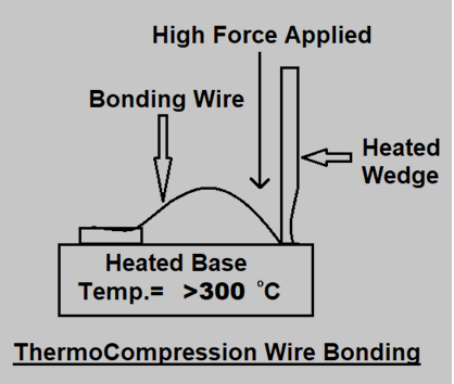
1) Thermocompression Wire Bonding:-
Thermocompression Bonding is also commonly known in the Semiconductor industry as Thermocompression Welding. It is performed using controlled time, heat, and forces to deform the wire and make a bond. The pressure, time, and temperature are the most important process parameters for this process. This bonding requires high temperature (normally above 300 degrees), high pressure (5000 to 10000 lb/sq in), and long bonding time for appropriate bonding.
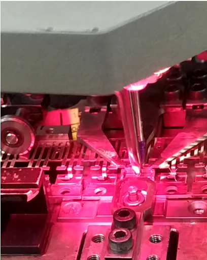
Due to their high diffusion rates, Copper, Gold, and Aluminum are the most widely used materials for Thermocompression Bonding. The below images show the process of Thermocompression Wire Bonding.
2) Ultrasonic Wire Bonding:-
In Ultrasonic Wire Bonding process, ultrasonic energy instead of heat is used to form a bond. This process works at low temperatures. In this process, thread the wire through a hole in the Wedge and trailing it under the bonding point. A clamp is used to hold it in place, and the bonding tool is placed over the first bond. The wire is pressed snugly between the wedge and the bond pad when the wedge is lowered.
A burst of ultrasonic energy is applied with the interface of compressive stress, a combination of pressure and vibration energy breaks down surface oxides and forms a bond. The below images show the process of Ultrasonic Wire Bonding.
a) Ultrasonic Wedge to Wedge Bonding:-
In the Ultrasonic Wedge to Wedge Bonding, the wire is fed through a hole in the back of a bonding wedge at an angle of 30 to 60 degrees from the horizontal bonding surface. A wedge-shaped tool flattens the wire and generates a weld below this point during wedge bonding of the wire. One bond is made to the die and another is to the substrate. The below images show the process of Wedge to Wedge Wire Bonding.
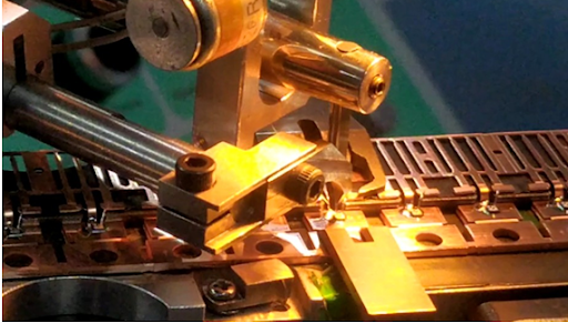
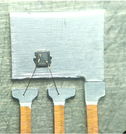
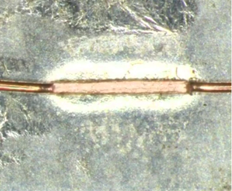
The below image represents the Wedge to Wedge Wire Bonding on the leadframe.
b) Ultrasonic Ball to Wedge Bonding:-
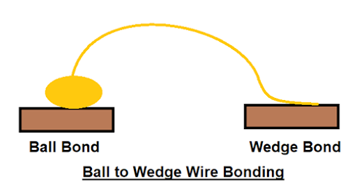
In this process, one edge of the capillary is used to form the all to wedge bond. The Ball Bond is made to the silicon chip and the subsequent wedge bond to the leadframe. The below image shows the process of Ball to Wedge Wire Bonding.
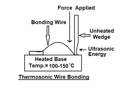
3) Thermosonic Wire Bonding:-
Thermosonic Wire Bonding is performed using ultrasonic energy, pressure, and heat to bond a wire to the surface of a substrate. In this process, the capillary is not heated and the temperature of the substrate is maintained between 100 to 150 degrees.
A burst of ultrasonic energy makes the bond. The diameter of the fine wire is typically less than 3 mils so the capillary can sufficiently deform the wire for easy separation. At the second bond, the capillary leaves a characteristic circular-shaped pattern which is known as a crescent bond. The Ball to Ball Wire Bonding is commonly used in the Thermosonic Bonding process.
The below image shows the process of Thermosonic Wire Bonding.
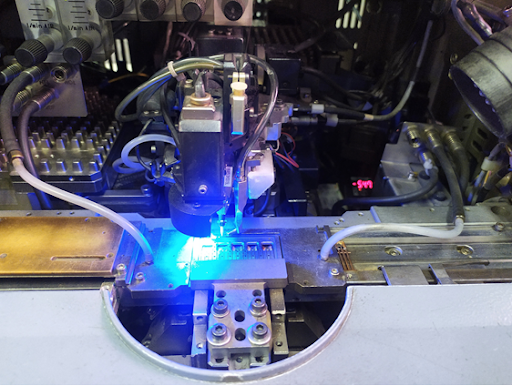
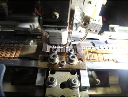
a) Ball to Ball Wire Bonding:-
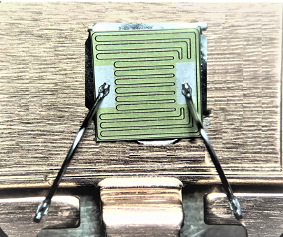
In this process, the bonding wire is passed through a Capillary tool which is mounted at the transducer, and a small portion of the wire is used to melt through an EFO (Electronic flame off system). A ball is formed on the end of the bonding wire and this ball is pressed to the bonding pad on the die with sufficient force then welded between two metal surfaces using a Capillary tool. The below image shows the process of Ball to Ball Wire Bonding on the leadframe.