SystemVerilog: Hướng dẫn cơ bản
In the realm of hardware design and verification, SystemVerilog stands as a titan among languages, beckoning engineers and developers with its robust capabilities. Originating from the fusion of Verilog with hardware verification languages, SystemVerilog’s evolution has revolutionized the world of electronic design automation (EDA). An introduction to SystemVerilog not only unfolds the story of its development but reveals the powerful tools it provides to the industry.
From its roots as an extension to Verilog to its current status as an IEEE standard, the history of SystemVerilog is a testament to its necessity and efficiency in modern circuit design and testing. Its hallmarks of enhanced syntax, improved readability, and seamless integration position it as an indispensable asset within engineering workflows. Whether you are a seasoned EDA veteran or a novice to hardware modeling, the journey through SystemVerilog’s landscape is bound to be enlightening.
This ‘Ultimate Guide to SystemVerilog’ serves as your roadmap, offering detailed insights about everything from setting up your coding environment to mastering the intricacies of modules and procedural blocks. With this guide, prepare to dive into the language’s sophisticated data types, operators, and constructs that shape the foundation of robust design and verification in the semiconductor industry.
What is SystemVerilog?
SystemVerilog is an advanced hardware description and hardware verification language. It extends the capabilities of its predecessor, Verilog, to meet the complex needs of Design and Verification engineers in electronic design automation (EDA). This IEEE Standard language incorporates verification features such as associative arrays, dynamic arrays, and formal verification constructs to validate the design’s behavior exhaustively.
Furthermore, SystemVerilog enhances the design process with classes that encapsulate data and functionality, making it easier to create modular verification environments. With constructs like initial and procedural blocks, verification engineers can simulate how a block of code executes over clock cycles in a simple testbench or complex verification system.
Key Features:
- Functional Coverage: Tracks the progress of verification scenarios.
- Class Properties: Allows for object-oriented programming techniques.
- Multi-Dimensional Arrays: Offers static and dynamic arrays for flexible data handling.
- Direct Programming Interface: Enables interaction between SystemVerilog and other programming languages.
SystemVerilog’s adoption is part of a larger aim to improve the reliability and efficiency of hardware design and verification tasks across the industry.
History and Development of SystemVerilog
SystemVerilog emerged as an amalgamation of Verilog, a popular hardware description language (HDL), with numerous verification features, fulfilling the industry’s demand for a robust Hardware Verification Language (HVL). Its development geared towards enhancing the capabilities of design engineers within the realm of Electronic Design Automation (EDA).
The Accellera Standards Organization initially spearheaded the standardization of SystemVerilog in 2002. The key objective was to refine and extend Verilog HDL to cover a more comprehensive design and verification flow. By 2005, SystemVerilog had evolved significantly, leading to its adoption as the IEEE Standard 1800.
This momentous leap integrated advanced features such as associative and dynamic arrays, class-based object orientation, and powerful assertions. With these enhancements, the language became a favorite tool among Verification engineers, enabling them to construct more sophisticated verification environments.
SystemVerilog’s expandability allowed incorporation of verification methodologies like Formal Verification, contributing to its widespread use. Coupled with the IEEE Design and Test of Computers journal’s documentation, the language’s development and applications have been thoroughly chronicled, reinforcing its integral role in modern hardware verification.
Design engineers now wield SystemVerilog confidently to tackle complex designs and verification challenges, making it an indispensable asset in EDA.
Benefits of SystemVerilog
SystemVerilog boasts a host of benefits that solidify its reputation as a powerful tool for both design and verification in electronic design automation. Its wide array of verification features provides a holistic approach to verifying complex designs with ease. Verification engineers are afforded enhanced capabilities with SystemVerilog, which aid in building a more robust and reliable verification process.
Enhanced Syntax and Features
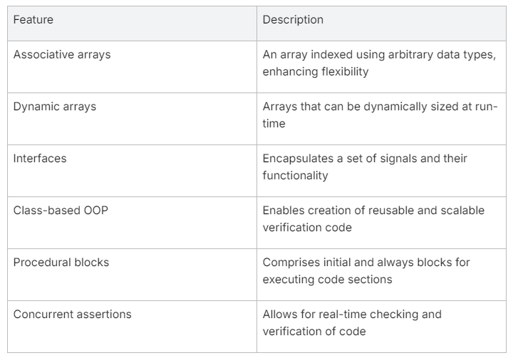
SystemVerilog encompasses a richer syntax and a suite of new features that elevate both hardware description and verification efforts. One among its many highlights is the inclusion of advanced data types such as associative arrays, dynamic arrays, and multi-dimensional static arrays. These allow for more flexible and intricate data storage and manipulation. The language introduces the concept of interfaces, which simplifies modular design and enhances encapsulation.
SystemVerilog’s verification arsenal is powered by class-based object orientation, promoting reusability and scalability in verification code. Class instances and properties facilitate structured and systematic verification builds. Procedural blocks, initial blocks, and concurrent assertions contribute to a comprehensive block of code that can handle a variety of simulation scenarios. The Direct Programming Interface further enables seamless interaction with external C/C++ code, broadening the scope for customization.
Here’s a glance at some key syntactic and feature enhancements:
Improved Readability and Maintainability
Another significant benefit of SystemVerilog is the improvement in the readability and maintainability of code. Its syntax is carefully designed to be both expressive and concise, reducing the chance for misinterpretation. Descriptive variable names and clear procedural statements enable quick comprehension of code functionality. The functional coverage capabilities let verification engineers write clearly defined goals for what needs to be tested, thereby reducing complexity and ambiguities in the verification process.
In the long run, SystemVerilog’s emphasis on readability means that codebases are easier to maintain. Engineers can confidently update and refactor verification environments, knowing that sound coding practices are already in place. Code written in SystemVerilog is easier to document, share with teammates, and hand off to others, thanks to its structured approach.
Seamless Integration with Existing Verification and Design Environments
One of the many reasons SystemVerilog has been readily adopted across the industry is its seamless integration with existing verification and design environments. Its compatibility with earlier versions of Verilog ensures a smooth transition for design engineers moving to SystemVerilog, without the need to discard existing codebases. Moreover, it lends itself well to established verification methodologies, such as Universal Verification Methodology (UVM), allowing for a synergistic incorporation into modern workflows.
By considering previous design paradigms, SystemVerilog facilitates a path for hardware description and verification processes to coexist and evolve together. This means engineers can iteratively bring SystemVerilog’s enhancements into their projects, integrating new tools and processes at a comfortable pace. Furthermore, SystemVerilog’s standardization under IEEE Standard 1800 means it is well-supported within Electronic Design Automation (EDA) tools, providing a stable foundation for design and verification tasks.
Overall, SystemVerilog provides a thorough and adaptable language framework that not only improves the quality of hardware descriptions and verification but also aligns well with existing methodologies and technologies, ensuring it remains central to the future of electronic design automation.
Getting Started with SystemVerilog
SystemVerilog is a potent extension of the Verilog hardware description language, tailored to address the increasingly complex task of designing and verifying digital systems. As an aspiring engineer or professional looking to harness the power of SystemVerilog, getting started involves familiarizing yourself with the language’s key concepts, its environment setup, and simulation processes. Below is a guide to help you begin your journey with SystemVerilog.
Setting Up the Environment
Before diving into writing SystemVerilog code, it’s essential to set up a proper development environment. This task generally involves selecting and installing an appropriate Electronic Design Automation (EDA) tool that supports SystemVerilog. Several tools exist, ranging from commercial offerings like Synopsys and Cadence to open-source alternatives like Icarus Verilog. Compatibility with SystemVerilog’s IEEE Standard 1800 should be confirmed while choosing a suitable tool for your development needs.
After choosing a tool, installation normally requires downloading the software from the provider, following their instructions for setup, and configuring it to your hardware specifications. The installation process might also involve setting up a license server for commercial software. Post-installation, it’s recommended to create a dedicated workspace that includes necessary libraries and directories where your SystemVerilog files will be stored and organized.
Compilation and Simulation
Once the environment is established, the next step is to compile and simulate your SystemVerilog models. Compilation transforms the high-level constructs of SystemVerilog into a form that is executable by a simulator. To compile SystemVerilog code, use the command-line interface or GUI provided by your EDA tool, specifying necessary options such as file paths, macro definitions, and compilation flags that might influence the simulation behavior.
After successful compilation, simulation can begin. The process of simulation usually involves the execution of a compiled design under specific test conditions to verify its functionality. Most tools offer a range of commands to control the simulation, such as starting, pausing, stopping, or viewing waveform results. Carefully understanding the feedback and results from a simulation is critical in determining if your design behaves as expected and meets the verification goals.
Basic Syntax and Structure
A solid grasp of SystemVerilog syntax and structure is vital for writing effective code. At its core, SystemVerilog is an enhancement of Verilog, adding a wide variety of constructs such as new data types, interfaces, and program blocks. Here is a basic outline of SystemVerilog structure and syntax tailored for easy readability:

A typical SystemVerilog file begins with declarations of modules or interfaces, followed by their respective internal code blocks containing procedural statements. The use of initial and always blocks aid in defining simulation behavior, while concurrent assertions check for conditions during simulation. Variables must be declared with appropriate data types, and clear naming conventions should be followed to enhance readability and maintainability.
Remember that while SystemVerilog offers robust verification features, starting with the basics and gradually incorporating more complex constructs will provide a solid foundation for understanding and utilizing this powerful language in both design and verification contexts.
SystemVerilog Data Types
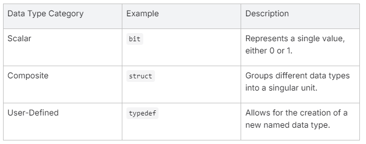
Understanding the various data types in SystemVerilog is crucial for any design or verification engineer. SystemVerilog provides rich sets of data types that are divided into scalar, composite, and user-defined categories. Each data type is designed to effectively model hardware behavior and to provide robust verification features.
Scalar Data Types
Scalar data types in SystemVerilog represent single values. They are typically used to model the simplest forms of data such as individual bits and boolean conditions. Some of the essential scalar data types are:
bit: Represents a single binary digit, which can be 0 or 1.logic: Similar tobit, but with a four-state logic that includes0,1,x(unknown), andz(high impedance).reg: A legacy from Verilog, intended for procedural assignments.int: A 32-bit signed integer.integer: A special variable-size data type mainly used for simulation.
Each scalar data type is designed to ensure precision and efficiency in various contexts of hardware modeling and simulation.
Composite Data Types
Composite data types allow users to aggregate multiple values. These are fundamental in creating more complex structures and memory models. SystemVerilog offers several composite data types, including:
- Arrays: Can be static, dynamic, associative, or multi-dimensional, allowing for a variety of memory structures.
- Structures (
struct): Enable the grouping of different data types into a single unit. - Unions (
union): Similar to structures, but they allow storage of different data types in the same memory location. - Strings: Provide the ability to use and manipulate text strings within testbenches or designs.
When defining hardware behavior or setting up verification environments, these composite data types play a significant role in managing and organizing data efficiently.
User-Defined Data Types
SystemVerilog goes a step beyond built-in data types by allowing designers and verification engineers to define their own data types. User-defined data types include:
typedef: Defines a new data type that is an alias for an existing data type or a composite data type.- Enumerations (
enum): Define a list of possible named values for a variable. - Classes: Object-oriented programming constructs that can encapsulate data and methods.
By defining custom data types, SystemVerilog allows for a higher level of abstraction and reuse. For example, a transaction class may be created to represent data transactions within a verification environment.
Grasping these data types provides a strong foundation for using SystemVerilog effectively. They enable design engineers to describe hardware modules precisely and verification engineers to create comprehensive test scenarios, thereby leveraging the full potential of electronic design automation.
SystemVerilog Operators
SystemVerilog, as an extension of the Verilog hardware description language, provides a broad spectrum of operators designed for complex hardware representation and verification functionality. Operators in SystemVerilog are used to perform calculations, make decisions, and manipulate data types efficiently. They can be classified into different categories based on their function: arithmetic, logical, bitwise, relational, conditional, and assignment operators. Each category is tailored to perform specific operations on the data, allowing both design and verification engineers to express the behavior of digital circuits with precision and control.
Arithmetic Operators
Arithmetic operators in SystemVerilog are used for performing common mathematical calculations. These operators are crucial in creating expressions that simulate various scenarios encountered in electronic design automation. The following are the primary arithmetic operators:
+: Addition operator adds two operands.-: Subtraction operator subtracts the second operand from the first.*: Multiplication operator multiplies two operands./: Division operator divides the first operand by the second.%: Modulus operator returns the remainder of a division operation.
Understanding and utilizing these operators allows device behavior modeling that accounts for mathematical calculations required in clock cycles, counters, or address arithmetic.
Logical Operators
Logical operators evaluate boolean conditions and are fundamental in control flow and decision making. They operate on boolean data types and provide the means to construct complex conditional statements. Here is a list of logical operators in SystemVerilog:
&&: Logical AND, returns true if both operands are true.||: Logical OR, returns true if at least one of the operands is true.!: Logical NOT, inverts the truth value of its operand.
By combining these logical operators, verification engineers can set up intricate verification scenarios and implement functional coverage cases.
Bitwise Operators
Bitwise operators in SystemVerilog operate at the bit level, which is useful when manipulating individual bits within data types like registers or wire arrays. The essential bitwise operators include:
&: Bitwise AND, performs logical AND on each pair of bits.|: Bitwise OR, performs logical OR on each pair of bits.^: Bitwise XOR, performs logical exclusive-OR on each pair of bits.~: Bitwise NOT, inverts each bit.
These operators are particularly important for design engineers when creating low-level hardware functions and control structures.
Relational Operators
Relational operators in SystemVerilog assess the relationship between two operands and are mainly used in conditional and looping statements. The primary relational operators are:
==: Equal to, checks if two operands are equal.!=: Not equal to, checks if two operands are not equal.>: Greater than, true if the left operand is greater than the right.<: Less than, true if the left operand is less than the right.>=: Greater than or equal to.<=: Less than or equal to.
Relational operators play a vital role in verification features, such as checking the output of a block of code against the expected values.
Conditional Operators
The conditional (ternary) operator is a unique operator in SystemVerilog that combines a condition with two values and selects one of the two values based on the condition’s outcome. The basic syntax is:
condition ? value_if_true : value_if_false
This operator is particularly useful for assigning a value to a variable based on a condition in a compact, easy-to-read manner and is often found in procedural blocks.
Assignment Operators
Assignment operators in SystemVerilog are used to assign values to variables. The simple assignment operator is =, but SystemVerilog also supports compound assignment operators that combine arithmetic or bitwise operation with assignment, such as +=, -= for arithmetic and &=, |= for bitwise operations. These operators streamline code and allow for concise expressions within initial blocks and always blocks.
In summary, operators in SystemVerilog provide the fundamental building blocks for constructing complex expressions and defining intricate behaviors in simulation and synthesis. Their proper application is essential for design engineers to accurately model hardware and for verification engineers to create effective verification environments.
Modules and Interfaces in SystemVerilog
SystemVerilog Modules and Interfaces serve as fundamental constructs for structuring and organizing complex designs and verification environments. Modules act as the basic building block in SystemVerilog hardware description, encapsulating functionality and promoting design reuse, while interfaces streamline the connection and communication between different modules. This design approach aligns with best practices in electronic design automation, enabling both design and verification engineers to work more efficiently.
Understanding Modules and Their Usage
Modules in SystemVerilog are akin to functions in traditional programming, but they represent a hardware block or component in a circuit. Each module defines a specific piece of hardware with inputs, outputs, and internal workings, and thereby captures the functionality and structure of digital logic. The usage of modules facilitates the hierarchical organization of complex systems, allowing designers to decompose systems into manageable, testable, and reusable parts.
Some of the key benefits of using modules include:
- Encapsulation: By encapsulating logic within a module, the internal complexities are hidden from other parts of the design, simplifying overall design management.
- Hierarchy: Modules allow for a tiered hierarchy within the design, making it easier to understand, modify, and maintain.
- Reusability: Once a module is defined, it can be instantiated multiple times within a design, enabling design reuse.
- Testability: Each module can be separately simulated and verified, making it easier to locate and fix problems.
A module might define a specific hardware component such as an ALU, a register file, or a multiplexer and would include definitions for its internal signals, procedural blocks, and sub-modules.
Creating and Instantiating Modules
Creating a SystemVerilog module involves defining the interface (ports), internal data types, and functionality through a combination of continuous assignments, procedural blocks, and lower-level module instantiations. The basic structure of a module declaration includes the module keyword, the module name, the port list, and the endmodule keyword. For example:
module MyModule (
    input logic clk,
    input logic reset,
    input logic [7:0] data_in,
    output logic [7:0] data_out
);

endmodule
Instantiating a module is akin to calling a function or creating an object instance from a class. When a module is instantiated, it is referred to as an instance, and each instance operates independently of others. Instantiation requires specifying the module name, instance name, and the connections to the instance ports, like so:
MyModule instanceName (
    .clk(systemClock),
    .reset(systemReset),
    .data_in(inputData),
    .data_out(outputData)
);
SystemVerilog Interfaces and Their Role
Interfaces in SystemVerilog simplify the management of complex signal connections between modules by bundling signals together into a single entity. Interfaces encapsulate the communication protocol and signal sets into a coherent unit, which can then be passed into modules. They are particularly beneficial in reducing the wiring complexity that can occur when there are numerous connections between modules, making modifications and maintenance much easier.
The role of interfaces is crucial in SystemVerilog, notably:
- Simplification: They simplify the connection between modules by using a single interface instance rather than multiple individual signals.
- Maintainability: Changing the communication between modules often requires altering just the interface, rather than the ports of every connected module.
- Clarity: Interfaces offer a clear picture of the inter-module communication protocols, enhancing readability and understanding.
The following snippet shows a simple interface definition and its implementation in a module instantiation:
interface BusInterface;
    logic [31:0] data;
    logic valid;

endinterface

module MyModule (
    BusInterface bus
);

endmodule


BusInterface busInstance;
MyModule modInstance(busInstance);
Leveraging modules and interfaces is a hallmark of advanced SystemVerilog usage, enabling better organized, scalable, and flexible designs that are easier to navigate and validate. This organization is imperative for efficient collaboration among design and verification engineers in the realm of ever-complex electronic design automation initiatives.
SystemVerilog Procedural Blocks and Statements
In SystemVerilog, procedural blocks are constructs that define a series of actions to be executed sequentially. These blocks are essential in describing the behavior of hardware during simulation. Unlike concurrent statements that occur simultaneously, procedural statements within these blocks are executed in the order in which they appear, closely mimicking the structure of software programs.
Initial Blocks
Initial blocks in SystemVerilog are used to define actions that are executed only once at the beginning of a simulation. This makes them perfect for setting up the initial state of a design or for running code that sets up testbenches. Inside an initial block, multiple procedural statements can be used, ranging from variable assignments to complex control flow instructions, such as loops and conditional evaluations.
For example:
initial begin

    reg_a = 0;
    reg_b = 0;

    start_test();
end
Always Blocks
Always blocks, on the other hand, are used to model combinational and sequential logic through repeated execution. They are invoked either by changes in sensitivity lists or by time-controlled events. Always blocks can represent digital circuits such as flip-flops, latches, or combinational logic gates within a hardware description.
- Combinational always block example:
always @ (a or b or c) begin

    y = a & b | c;
end
- Sequential always block example:
always_ff @ (posedge clk) begin

    if (reset)
        q <= 0;
    else
        q <= d;
end
Case Statements
SystemVerilog’s case statements allow decision-making based on the value of a variable or expression, executing different blocks of code depending on the case value. They provide clarity and conciseness in conditional operations, facilitating multiple unique paths of execution within procedural blocks. Additionally, SystemVerilog offers unique case (casez, casex) statements to handle don’t-care conditions or to match a range of values.
For example:
case (opcode)
    ADD: result = operand1 + operand2;
    SUB: result = operand1 - operand2;
    MUL: result = operand1 * operand2;
    default: result = 'bx;
endcase
The case statement’s power and flexibility make it an important component of writing clear and effective SystemVerilog code, especially in scenarios with complex conditional logic.