Bird's Eye View Magic: Cadence Tensilica Product Group vén bức màn bí mật
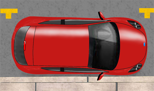
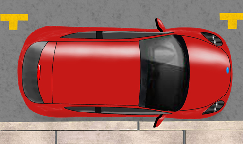
Even for experienced technologists some technologies can seem almost indistinguishable from magic. One example is the bird’s eye camera view available on your car’s infotainment screen. This view appears to be taken from a camera hovering tens of feet above your car. As an aid to parallel parking, it’s a brilliant invention; you can see how close you are to the car in front, the car behind, and to the curb. Radar helps up to a point with the first two, not so much with close positioning or the curb. A bird’s eye view (BEV) makes all this easy and, better yet, intuitive. No need for you to integrate unfamiliar sensory inputs (radar warnings) with what you can see (incompletely) from your car seat. A BEV provides an immediately understandable and precise view everywhere around the car – no blind spots.

Image courtesy of Jeff Miles
The basic idea has its origins in early advances in art: an understanding of perspective developed in the 15th century from which projective geometry emerged in the 17th century. Both are concerned with accurately rendering 3D images on a plane from a fixed perspective. In BEV the input to this process starts with wide-angle images from around the car, stitched together for a 360o view, and projectively transformed onto the focal plane of an imaginary camera sitting 25 feet above the car. This is the heart of the BEV (bird’s eye view) trick. I offer a highly condensed summary below.
First capture surround view images
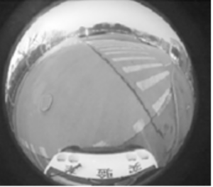
Most modern cars have at least one camera in front and one in the rear, plus cameras in the (external) side mirrors. These commonly use fisheye lenses to get a wide-angle view. Each image is highly distorted and must be processed through a non-linear transformation, a process known as de-warping, to recover an undistorted wide-angle image.

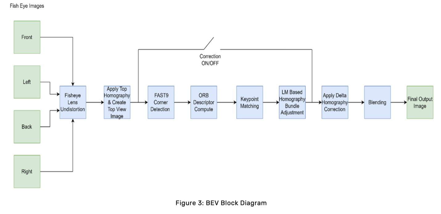
The full BEV flow is pictured below starting with de-warping (un-distortion) and projection (homography). Cameras are organized so that images have some overlap. Here let’s assume that the cameras are labeled north, south, east and west, so north has some overlap with west, a different overlap with east and so on.
These overlaps allow for calibration of the system since a key point that appears in say north and west images should map to a common point in the top-view plane. Calibration is accomplished by imaging with the car parked on a simple pattern like a grid. Based on this grid, common key points between de-warped images can easily be matched allowing projection matrices to be computed, between the top plane and each of the (de-warped) camera planes.

So far this will develop a reliable top image in calibration at the factory but should self-check periodically and fine-tune where needed (or report need for a service). We’ll get to that next. First, since images overlap and may have different lighting conditions, those overlaps must be “blended” to provide seamless transitions between images. This is a common function in computer vision (CV) libraries.
In-flight self-checking is a common capability in ASIL-D designs and here extends beyond low-level logic checks to check continued consistency with the original calibration. Very briefly this works by identifying common image features seen in overlaps between cameras. If the calibration is not completely accurate artifacts will be seen in edges not aligning, or blurring, or in ghost images. The self-checking flow will (optionally) find and correct for such cases. Amol Borkar (Automotive Segment Director, DSP Product Management & Marketing at Cadence) tells me that such checks are run periodically as you would expect, but the frequency they are run at varies between applications.
All these transformations, from de-warping through to blending, are ideally suited to CV platforms. The Cadence Tensilica Products Group has released a white paper on how they implement BEV in their Tensilica Vision product family (namely the Vision 240 and Vision 341 DSPs)
Also interesting is that AI is expected to play an increasing role in building the 3D view around the car, not only in analyzing the view once built. The BEV concept could also extend to car guidance perhaps with AR feedback to the driver. Exciting stuff!
You can read the Cadence white paper HERE.
Also Read:
Intel and Cadence Collaborate to Advance the All-Important UCIe Standard
Bug Hunting in NoCs. Innovation in Verification
Overcoming Verification Challenges of SPI NAND Flash Octal DDR
Share this post via:
